How To Make An Automatic Feeding System For Your Pets?
The pets need to be fed timely so that they could maintain good health. The pet owners aren’t available at the home 24/7, sometimes they go for business meetings to another city or someone else’s house so, the pets suffer in their absence due to lack of food. The gravity feeders are available in the market that can feed the pets automatically but they are a bit expensive and they require a large area for placement. Today, I will design an automatic feeding system for domestic pets that will minimize the human efforts of feeding the pets to a large extent. The one would place the food in the container and it will be automatically refilled as soon as falls below a certain level. Hence, follow this tutorial and be ready to implement this innovative idea at your homes.
How To Set up The Apparatus And Automate It Using Arduino?
The purpose of this technique is to make a system, more effective from the systems available in the market like gravity feeders, with comparatively low cost. Our system will be responsible for maintaining the constant supply of food and water both to the pets. Firstly, we will design the automatic water feeding system and secondly, we will design an automatic food feeder for our pets.
Step 1: Components Needed (Hardware)
- Arduino UNO
- 5 Gallon Water Container
- LCD 1602 Module
- Jumper Wires
- Natural Bamboo Sticks
- Breadboard
- Tactile Push Button Switch
- BC547 Transistors (x4)
- No products found.
- DS3231 RTC Module
- 4x4 Matrix Keypad Membrane
- 470k Ohm Resistor (x8)
- 33 Ohm Resistor (x8)
- Printed Circuit Board
- Soldering Iron
- Hot Glue Gun
- No products found.
- FeCl3
Step 2: Components Needed (Software)
Before assembling the circuit on the hardware it should be simulated. After the simulation, we come to know that whether our circuit will work accurately or not. Hence, I have included the software simulations below and for that, the software required is Proteus Professional.
- Proteus 8 Professional (Can be downloaded from Here)
Step 3: Working Principle Of Autonomous Water Pumping System
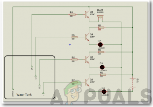
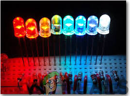
Among all of the components, the most important components are Transistors BC 547. There are a total of 7 transistors and they will be sensing the water level. LED’s will be monitoring the water level in the Container. as the water ascends the sensors begin to get in contact with the water and the transistors are activated and there is a progression of current in the transistors making the LED’s light up. There is a current limiting resistor involved between transistor and LED and it prevents higher voltage to enter the LED. The rubber pipe will be connected to the overhead tank and it will be responsible for filling the container as the level is dropped below a certain threshold. As the water drops below the threshold the water pump starts and the container starts to fill. In this way, there is no need to refill the container manually and pets are supplied with the constant supply of water. For your ease, I will elaborate on the functionality of LEDs. The LEDs installed in the circuit are of four types of colors. Red, Yellow, Green, and Blue. The red one indicates that there is no water in the container and none of the sensors is in contact with the water and the container needs to be refilled. The yellow LED indicates 1/4 of water in the container. The green LED indicates that the container is half full of water and the blue LED indicates that the container is full of water.
Step 4: Simulating the circuit
- After you download and install the Proteus software, open it. Open a new schematic by clicking the ISIS icon on the menu.
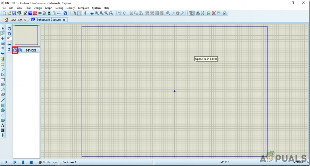
New Schematic - When the new schematic appears, click on the P icon on the side menu. This will open a box in which you can select all the components that will be used.
- Now type the name of the components that will be used to make the circuit. The component will appear in a list on the right side.
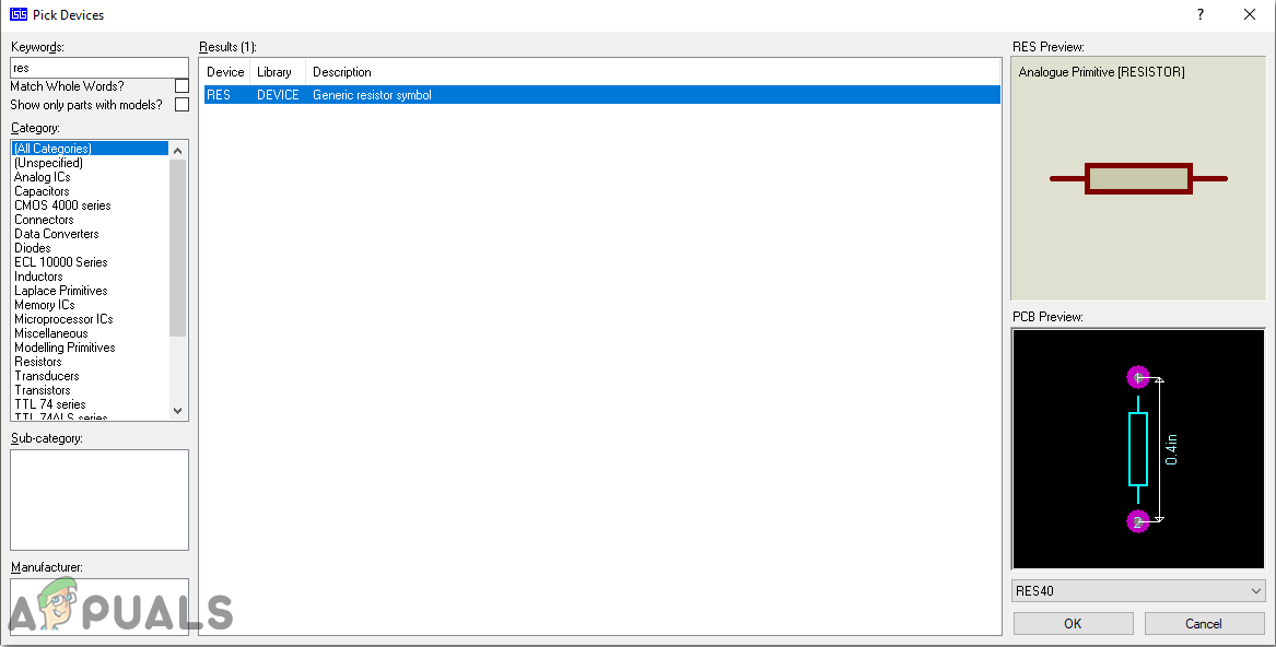
Selecting Components - In the same way, as above, search all the components as above. They will appear in the Devices List.
Step 5: Make a PCB Layout
As we are going to make the hardware circuit on a PCB, We need to make a PCB layout for this circuit first.
- To make the PCB layout on Proteus, we first need to assign the PCB packages to every component on the schematic. to assign packages, right mouse clicks on the component you want to assign the package and select Packaging Tool.
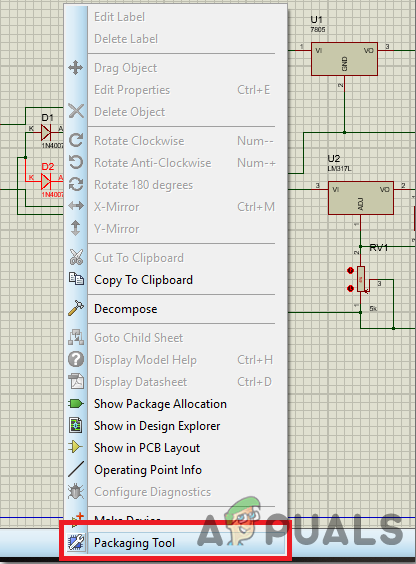
Assign Packages - Click on the ARIES option on the top menu to open a PCB schematic.
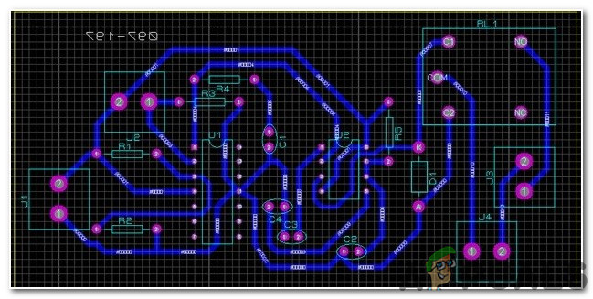
ARIES Design - From the Components List, Place all the components on the screen in a design you want your circuit to look like.
- Click on the track mode and connect all the pins that the software is telling you to connect by pointing an arrow.
Step 6: Circuit Diagram
After assembling the components and wiring them the circuit diagram should look like this:
Step 7: Working Principle Of Autonomous Food Supply System
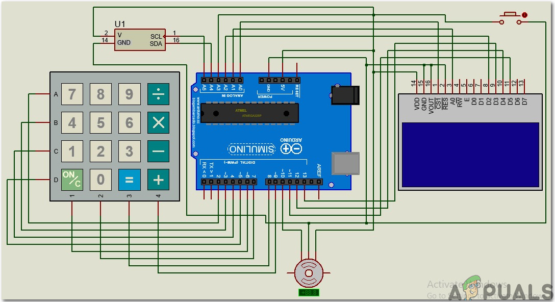
The working principle of the food supply system is very simple and the most vital component in this circuit is the Real-Time Clock Module (DS3231) through which we are able to set the date and time at which food will be served to our pets. The LCD module will display the date and time and the servo motor will rotate the bowls that will be comprised of food. I have included the 4×4 keypad to manually set the time for feeding the pets. I have used the servo motor so that the bowl containing the food can be rotated and it could be dropped into the lower bowl from where the pets will be able to eat it. The food will be dropped into the lower bowl at the specific intervals set that will be set by you in the code. You can set the quantity of food on your own keeping in view the habits of eating the dog, cat, parrot, etc.
Step 8: Simulating The Circuit
Simulate the circuit by following the steps above to check whether it is working or not. The rest of the procedure is the same except the components and their placement. The components that will be used in the circuit are shown below:
- The components will appear in the Devices List.
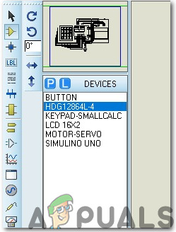
Components Used
Now, as we have checked that the circuit is working fine we will proceed further and write the code for Arduino.
Step 9: Circuit Diagram
The circuit diagram of Proteus should look like this:
Step 10: Getting Started With Arduino
If you are not familiar with Arduino IDE before, don’t worry because below, you can see clear steps of burning code on the microcontroller board using Arduino IDE. You can download the latest version of Arduino IDE from here and follow the steps below:
- When the Arduino board is connected to your PC, open “Control panel” and click on “Hardware and Sound”. Then click on “Devices and Printers”. Find the name of the port to which your Arduino board is connected. In my case it is “COM14” but it may be different on your PC.
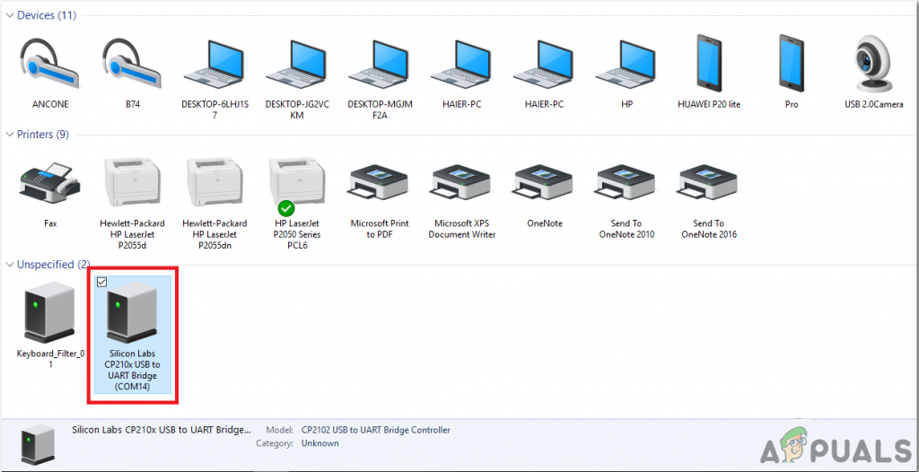
Finding Port - Now open the Arduino IDE. From Tools, set the Arduino board to Arduino / Genuino UNO.
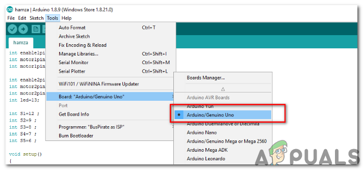
Setting Board - From the same Tool menu, set the port number that you saw in the control panel.
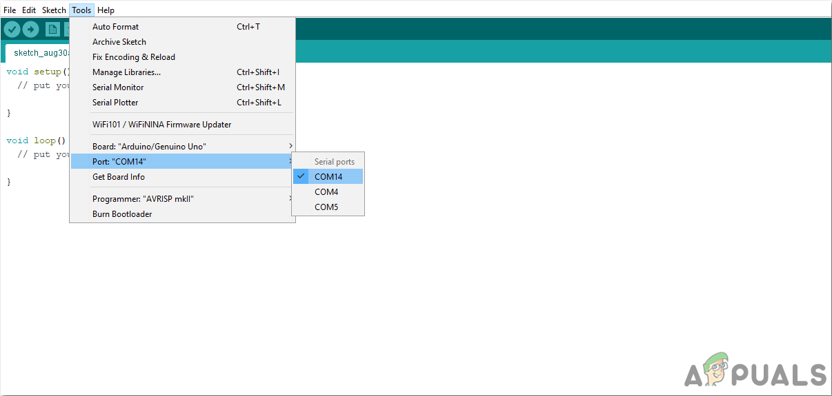
Setting Port - Download the code attached below and copy it to your IDE. To upload the code, click on the upload button.
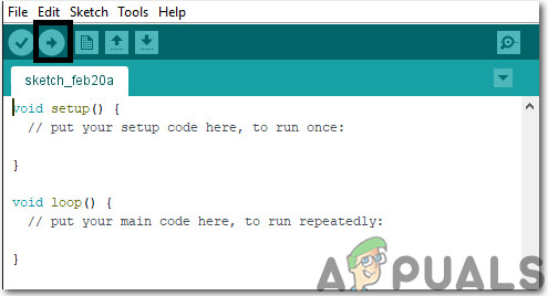
Upload The Code
You can download the code from Here.
Step 11: Understanding The Code
The code used in this project is very simple and well commented. Although it is self-explanatory, it is briefly described below so that if you are using a different Arduino board like nano, mega, etc you can modify the code properly and then burn it onto your board.
- At the top, different libraries are included so that keypad, LCD, RTC IC, and servo motor can be operated by the microcontroller.
#include <DS3231.h>
#include <Servo.h>
#include <LiquidCrystal.h>
#include <Keypad.h>
2. Then the rows and columns of the keypad have initialized the pins of Arduino they will be connected to and then the whole keypad is created.
const byte ROWS = 4; // Four rows
const byte COLS = 4; // Three columns
// Define the Keymap
char keys[ROWS][COLS] = {
{'1','2','3','A'},
{'4','5','6','B'},
{'7','8','9','C'},
{'*','0','#','D'}
};
byte rowPins[ROWS] = { 2, 3, 4, 5 }; // Connect keypad ROW0, ROW1, ROW2 and ROW3 to these Arduino pins.
byte colPins[COLS] = { 6, 7, 8, 9 }; // Connect keypad COL0, COL1 and COL2 to these Arduino pins.
Keypad kpd = Keypad( makeKeymap(keys), rowPins, colPins, ROWS, COLS ); // Create the Keypad
3. Then the RTC IC, servo motor and the Liquid LCD are initialized and some variables are declared that will be used for the run-time calculations.
DS3231 rtc(A4, A5);
Servo servo_test; //initialize a servo object for the connected servo
LiquidCrystal lcd(A0, A1, A2, 11, 12, 13); // Creates an LC object. Parameters: (rs, enable, d4, d5, d6, d7)

//int angle = 0;
// int potentio = A0;      // initialize the A0analog pin for potentiometer
int t1, t2, t3, t4, t5, t6;
boolean feed = true; // condition for alarm
char key;
int r[6];
4. void setup() is a function that is executed only once in the code when the microcontroller is powered up or the enable button is pressed. The baud rate is set in this function which is basically the speed in bits per second by which the microcontroller communicates with the peripheral devices. In this function, RTC and the servo are also started and the pins are initialized to be used as Input or Output.
void setup()
{
servo_test.attach(10); // attach the signal pin of servo to pin9 of arduino
rtc.begin();
lcd.begin(16,2);
servo_test.write(55);
Serial.begin(9600);
pinMode(A0, OUTPUT);
pinMode(A1, OUTPUT);
pinMode(A2, OUTPUT);
}
5. void loop() is a function that is executed again and again in a loop. Here in this function, the code is written to keep track of time and print it on the LCD. then a command is given to rotating the servo at a specified angle.
void loop()
{
lcd.setCursor(0,0);
int buttonPress;
buttonPress = digitalRead(A3);
if (buttonPress==1)
setFeedingTime();

//Serial.println(buttonPress);
lcd.print("Time: ");
String t = "";
t = rtc.getTimeStr();
t1 = t.charAt(0)-48;
t2 = t.charAt(1)-48;
t3 = t.charAt(3)-48;
t4 = t.charAt(4)-48;
t5 = t.charAt(6)-48;
t6 = t.charAt(7)-48;
lcd.print(rtc.getTimeStr());
lcd.setCursor(0,1);
lcd.print("Date: ");
lcd.print(rtc.getDateStr());

if (t1==r[0] && t2==r[1] && t3==r[2] && t4==r[3]&& t5<1 && t6<3 && feed==true)
{
servo_test.write(100); //command to rotate the servo to the specified angle
delay(400);
servo_test.write(55);
feed=false;
}
}
6. void setFeedingTime() is a function that takes input from the keypad and maps the input to set the feeding time in the microcontroller. This time is later used to rotate the motor to feed the pets.
void setFeedingTime()
{
feed = true;
int i=0;
lcd.clear();
lcd.setCursor(0,0);
lcd.print("Set feeding Time");
lcd.clear();
lcd.print("HH:MM");
lcd.setCursor(0,1);

while(1){
key = kpd.getKey();
char j;
if(key!=NO_KEY){
lcd.setCursor(j,1);
lcd.print(key);
r[i] = key-48;
i++;
j++;
if (j==2)
{
lcd.print(":"); j++;
}
delay(500);
}
if (key == 'D')
{key=0; break; }
}
}
Step 12: Hardware Design Of Water Pumping System
As we have done all the software tasks now let’s proceed towards designing the hardware of the project. First of all, we will assemble the components of the water pumping system and afterward, we will design the hardware of the automatic food supply system. After making a PCB layout of the circuit solder the components on the PCB board according to the circuit diagram shown above. Put the circuit in a small box and make holes in it appropriately so that LED’s may come out of the box easily. Take a PCB board and solder the LED’s on it according to the levels defined above. After analyzing the circuit we came to know that five supply lines need to be taken out from the main circuit board to the sensor. Four lines are of the sensors and one is for Common Positive Pin.
We possibly need to make two channels so when they are in contact with water they will go about as a switch, as water is a good conductor of electricity. We can use a PVC pipe and make holes in it. Firstly, measure the height of the container and then with equal intervals mark 4 points on it. Make holes on those points and then make a loop of wire which will be carrying the current. Fix that loop of wire with nuts and bolts in that PVC pipe and afterward add a common wire to the casing. The hole of the bare wire and bolt should be kept a minimum and in the event that you need, you can solder a little bit of wire to the common line just next to the nut and screw as the sensing would be more at the point when the water interacts with the normal wire and the bolt, there will be a transfer of current from the stripped wire to the bolt and hence, the sensing part is complete. As soon as the water comes below a certain level the water motor is turned ON and the tank starts filling. As the tank starts filling the container also starts filling due to the water pipe as water is transferred from the tank to the container through the pipe. Hence, there is no need to manually fill the container anymore.
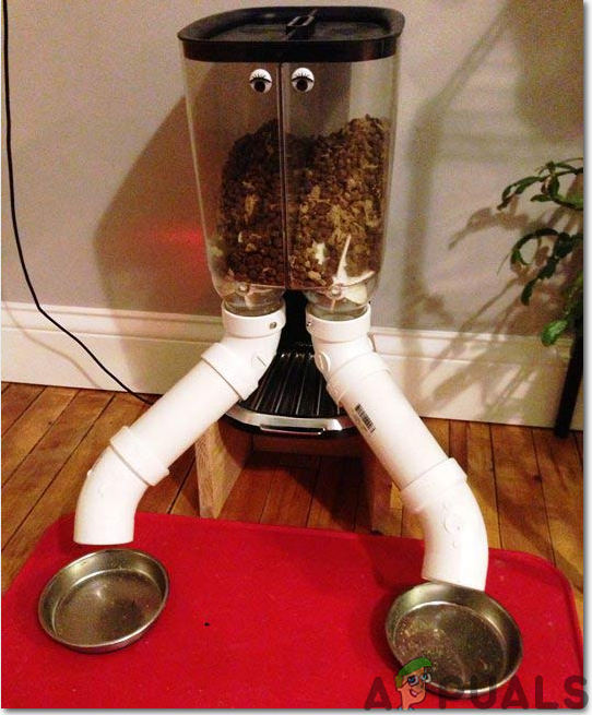
Step 13: Hardware Design Of Automatic Food Supply System
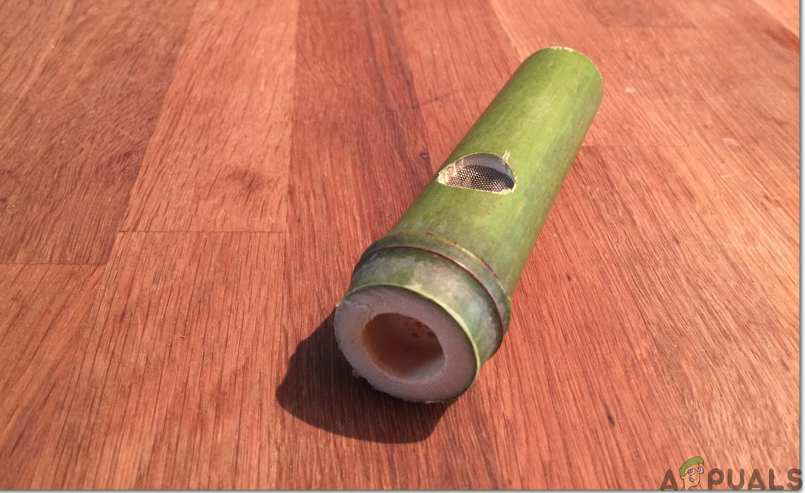
Now we will assemble the hardware of the food supply system. We can set the time intervals of our own choice by using the DS3231 Real Time Clock module and hence keeping in view the eating schedule of our pets we will adjust the schedule. When the timer will reach the set date and time the servo motor will move and the food will be dropped into the bowl placed below. Assemble the circuit as shown above on the breadboard. Take a wooden stick and attach the servo motor with it. Fix it vertically against the wall and with the help of screws attach the bowl of food to the stick. Bowl can be like a bamboo-shaped hollow pipe open from both ends and a round wooden piece will be placed at the bottom of it. The servo motor will be attached to the wooden piece and as soon as the motor moves at some angle the food is dropped in the bowl placed below.
That’s all for today. Don’t forget to share your experience after completing this project and if you have any issues while making it feel free to ask in the comment section.