How To Make A Digital Air Pollution Meter Using Arduino?
The major hazard that can affect humanity these days is pollution. Today we will design an Air Pollution meter that will be used to monitor the air quality on our smartphone. The backbone of this project is the Arduino Board and the Blynk Application that can be easily downloaded from Playstore.
How To Monitor Air Pollution On Mobile?
Step 1: Gathering The Components
Making a complete list of all the components before start working on any project has always been an excellent approach. It not only saves a lot of time but also saves us from getting stuck somewhere in the middle of the project by letting us know that whar components are easily available and what components are to be bought from the market. Below is a complete list of all the components that we are going to use in our project. These components are easily available in the market.
- Arduino Uno
- 5V Relay Module (x2)
- Gas Sensor MQ135
- PM2.5 Sensor
- Arduino Ethernet Shield
- No products found.
- Female Headers
- No products found.
- 2 Pin Connectors (x3)
- No products found.
- 12V Battery
- No products found.
- Connecting wires
Step 2: Design Of The Circuit
As we now know the main abstract of our project, and we also have a complete list of all the components that we are going to use in this project, let us move a step further and see the design of the project. The project is mainly divided into two parts. The first part is the Controller and Sensors and the second part is the Smartphone application.
The heart of the project is its microcontroller. Arduino Uno is the microcontroller used. The Arduino board is connected to the Blynk cloud using an Internet connection which is established by using Arduino Ethernet Shield. The sensors that are used in this Pollution meter are nova PM sensor SDS011, Gas sensor MQ135, and temperature and DHT11.
The smart meter is made using an Android phone so that all the readings can be seen on the mobile screen and this mobile can be used to control the relays in the hardware. Blynk is a mobile application that can be used on android and IOS. It is well designed and it contains widgets that can be easily used. This application saves a lot of money and time because the hardware of the LCD and other components are to be bought from the market whereas this application is free and can fulfil the task that is to be carried out by those hardware components.
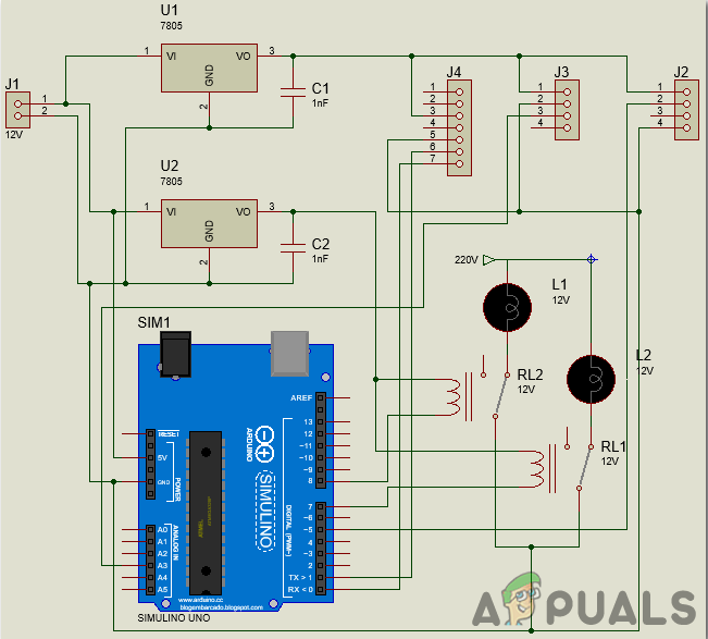
Step 3: Working Of The Circuit
In this section, we will go through a brief study of the working of our circuit. Our circuit includes an Arduino board with an Arduino ethernet shield, Voltage regulators 7805, Temperature and humidity sensor DHT11, Gas sensor MQ135, Relay modules, and PM2.5 sensor along with some other components. You can also use the PM10 sensor instead of PM2.5.
PM stands for Particulate Meter. This sensor has a mixture of dust particles and water droplets in it. A specific source directly releases some of these particles whereas a specific chemical reaction is used to produce other particles. The principle of laser scattering in the air is used in this sensor to detect suspended particles in the air. These particles’ concentration can range from 0.3 to 10 microns. This sensor is robust and gives stable and sensitive data. It is connected across the Tx and Rx of the Arduino Uno board.
The gas sensor works on the principle in which the conductivity changes with the change in the concentration of gas. it gives a voltage signal as an output which is directly related to the concentration of the gas. This sensor is highly sensitive to ammonia, sulfide, and benzene steams, smoke and other harmful gases.
The temperature sensor senses the temperature and humidity of the surroundings and sends a voltage signal to the microcontroller. It is robust and gives data with minimum error.
These all sensors are assembled together with the microcontroller and are continuously sending data to the microcontroller. Two appliances i.e. fan and the light are connected to the controller through a relay module. These two will be working as an alarm indication and control.
Step 4: Working Of Blynk
Blynk is a mobile application that can be downloaded on Android as well as IOS sets. It is used to display data and visualize it that is sent to the cloud from the hardware sensors. The three major components of Blynk is its mobile application, Blynk cloud, and Blynk libraries.
Blynk app is the front end application that is installed on the mobile phone. It contains various widgets that allow you to design exciting projects. This app is very user-friendly and easy to use.
The Blynk cloud is a kind of database that is responsible to connect the hardware to the mobile application. You can run your own private Blynk server locally using this Blynk cloud. This cloud is open-source. Thousands of devices can be connected to the cloud but this server can only be made using a Raspberry Pi.
Libraries for various sensor components are available that are used to connect them with the server. These libraries are responsible to control all the data that is coming from the sensors or going out of the application. When a button is pressed on the application, some data is sent to the Blynk cloud and then it is sent to the corresponding hardware. Similarly, the data from the sensor is sent to the cloud using an internet connection and then it fetched from the cloud and displayed on the mobile application.
Step 5: Connecting the Circuit
Presently as we have every one of the parts and we know precisely what is the primary working guideline of the framework, we can move forward and start assembling our segments together. One thing must be remembered that the circuit must be minimized and the segments must be set close.
- Take a Veroboard and rub its side with the copper coating with a scraper paper.
- Now Place the components carefully and close enough so that the size of the circuit does not become very big
- Cut pieces of female headers for every sensor and place them on the Veroboard. All the sensors will be inserted in these female headers.
- Carefully make the connections using solder iron. If any mistake is made while making the connections, try to desolder the connection and solder the connection again properly, but in the end, the connection must be tight.
- Once all the connections are made, carry out a continuity test. In electronics, the continuity test is the checking of an electric circuit to check whether current flow in the desired path (that it is in certainty a total circuit). A continuity test is performed by setting a little voltage (wired in arrangement with a LED or commotion creating part, for example, a piezoelectric speaker) over the picked way.
- If the continuity test passes, it means that the circuit is adequately made as desired. It is now ready to be tested.
- Connect the battery to the circuit.
Step 6: Getting Started With Arduino
Arduino IDE is a software on which you can write, debug, and compile a code that will run on an Arduino microcontroller. This code will be uploaded to the microcontroller through this IDE. IF you have no previous experience with this software, there is nothing to worry about because the whole procedure to use this software is given below.
- If you don’t have the software already installed, click here to download the software.
- Connect your Arduino board to the PC and open Control Panel. Click on Hardware and Sound. Now open Devices and Printer and find the port to which your board is connected. This port is different on different computers.
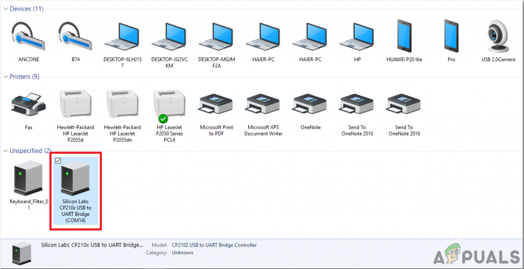
Finding Port - Now open the Arduino IDE. From Tools, set the Arduino board to Arduino / Genuino UNO.
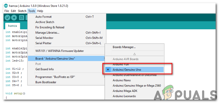
Setting Board - From the same Tool menu, set the port number. This port number should be exactly the same as the port number that was observed before in the control panel.
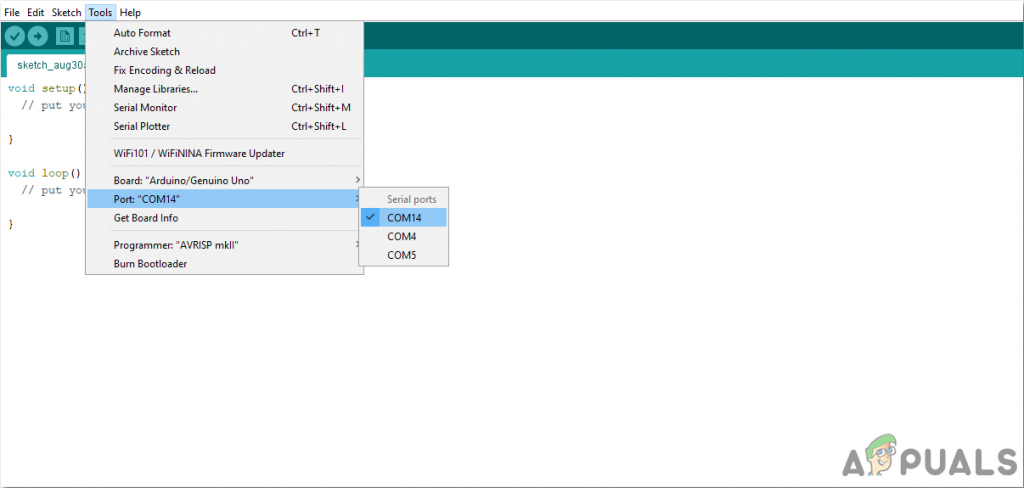
Setting Port - Now, to use the Blynk application and ethernet shield with Arduino IDE, we need to import special libraries that will allow us to burn code on Arduino Uno and use it. These two libraries are attached in the link given below. To include the library, goto Sketch > Include Library > Add ZIP Library. A box will appear. Find the ZIP folder on your computer and click OK to include the folders. This library is attached along with the code in the link below.
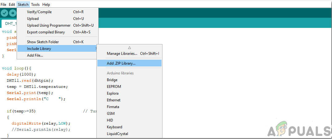
Include Library - Download the code attached below and copy it to your IDE. To upload the code, click on the upload button.
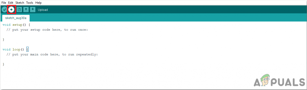
Upload
To download the code, click here.
Step 7: Configuring The Application
Now as we have connected the circuit, let us download and install the Blynk application from the play store. Follow the steps below to set up the digital dashboard.
- Mount the ethernet shield on Arduino.
- Connect this board to your personal computer.
- Open the sketch ethernetclient.ino and add the IP address of your device. After doing this, upload the code on the Arduino board. A google search will be returned by this sketch and the results are viewed on the serial monitor as an HTML.
- Open the sketch ethernetserver.ino and add the IP address of our device. Then upload this sketch on your Arduino board. This sketch will create a web server using Arduino and the ethernet shield. Now an HTTP request will be answered by your device. In this sketch, the internet browser will be able to get the data that is being sent by your Arduino through an ethernet shield.
- Now make sure your mobile has an active Wifi connection. Launch the Blynk application that you have already downloaded. Create a new account on this application. An account will be created to save your projects.
- After the account is created, sign in to your account and create a new project and name it as Pollution Meter. After doing this, select the microcontroller as Arduino Uno. Choose your connection as Ethernet.
- When you click on the Create button, an authentication key will be sent to your registered email. This authentication key is a unique key that helps to connect the smartphone to your hardware. Paste this authentication key in the Arduino sketch names as pollution.ino.
- When this is done, Open the pollution.ino sketch in Arduino IDE and upload it on the Arduino board.
- When the project is created in the android application, an empty canvas will appear on the screen.
- Tap anywhere on the screen. A widget box will appear containing all the widgets that can be used in the application.
- From the Widget menu, select the LCD and place it on the main layout. Similarly, place an LED, RTC widgets, Pushbutton and an ON/OFF switch, on the main layout.
- When everything is done, click on the play button. In this play mode, your app will be communicating with the hardware in real-time. You will be able to see the data on LCD and control the relays of the hardware from your mobile.
Step 8: Working of Sketches
The code for this project is very complicated and divided into different sketches. You need to study it in depth to maintain the sequence of uploading if u want your project to work properly. Some chunks of the code are briefly explained below.
1. ethernetclient.ino is an Arduino sketch that is used to connect the board to the “www.Google.com” website using an Ethernet shield. In this sketch, the mac address of your ethernet shield is included. This MAC address is given on the sticker behind the board. The website and its IP, to which the board is to be connected is also given in this sketch. In the body of void setup(), the connection of the board to the destination website is established. An error message is given if the connection fails. In the void loop() if there are any incoming bytes from the server, they are read and then printed on the serial monitor.
2. ethernetserver.ino is an Arduino sketch that is a simple web server that shows the value of the analog input pins using an Arduino Wiznet Ethernet shield. In this sketch also, the mac address of your ethernet shield is included. The IP address of the local network will also be included here. In void setup() the serial communication is opened and then the microcontroller waits for the port to open. When it is done the microcontroller waits for serial port to connect and then the ethernet connection is started. In void loop() the microcontroller listens for incoming clients. When the incoming request is completed, a reply can be sent. So a standard HTTP response header is sent and after this response is completed, the connection will be automatically closed. After this, the data that is being read from the analog pins, it sends it as the output. when all the data is sent to the web browser, the connection will be closed.
3. BlynkBlink.ino is an Arduino sketch that is used to connect the Blynk app to the hardware. The authentication key is added to this code that was provided by the application through an email. in this sketch void setup() is setting the baud rate of the microcontroller and it is connecting the hardware to the Blynk cloud using the authentication key.
#define BLYNK_PRINT Serial                        // Enables Serial Monitor
#include <SPI.h>
#include <Ethernet.h>
#include <BlynkSimpleEthernet.h>                  // This part is for Ethernet stuff
char auth[] = "117a820688214b22b7baf59f8d63c492"; // Put your Auth Token here.
void setup()
{
 Serial.begin(9600);                              // Setting the baud rate
 Blynk.begin(auth);                               // connecting the arduino board to the Blynk Cloud.
}

void loop()
{
 Blynk.run();                                     // Blynk works here
}