Controlling Your Stove From Your Smartphone Using WiFi
In the modern world, if we look around, we can see that everything that includes electronics is automated to some extent. Home automation systems or smart homes are very common nowadays. By using these systems different home appliances can be automated using a mobile application. But most of these systems do not include anything that automates your gas stove. In this article, we are going to develop a system that will allow you to control your gas stove by using a mobile application. This application will be used to open or close the gas valve from the main valve and to ignite the spark plug to build the fire.

How To Automate Gas Stove Through Your Mobile?
Now as we know the abstract of the project, let us move forward and gather different information to start working. We will first make a list of the components and then assemble all the components together to make a working system.
Step 1: Gathering The Components
Before starting any project, if we want to avoid the fear of getting stuck in the middle of the project, we should have a complete list of all the components that we will need while working on the project. This is an excellent approach that saves a lot of time and effort. A complete list of all the components that are used in this project is given below. All these components are easily available in the market.
- ESP32
- Gas Valve for Arduino
- No products found.
- No products found.
- 5V Relay Module
- 2N2222 NPN Transistor
- No products found.
- 10k-ohm Resistor
- No products found.
- 5V Spark Plug
Step 2: Developing An Android Application
As we are going to control this stove using an android application, we need to develop it first. Previously, we have developed several android applications. Previously, we have made an application that consists of only one button in it. This button is used to send data into the database. If ‘1’ is inserted into the database, the relay will be turned on and if ‘0’ is inserted into the database, the relay will be switched off.
We will make a little amendment in this application. By following the same procedure that was followed to make the first button and connect it to the firebase, we will make another button that will be connected to the firebase.
One button will be used to open and close the gas valve and the second button will be used to create a spark that will be responsible for the ignition.
Step 3: Making The Circuit
As we now know the main crux of this project, let us assemble all the components together to make a final circuit.
Take a breadboard and insert the ESP32 board in it. Take both transistors and resistors and insert them in the breadboard in such a way that the transistor can be used as a switched. Follow the configuration below so that you don’t make any mistakes while making the switch.
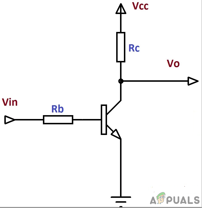
In the above figure, connect the Vin port to the pins of the ESP32, connect the port Vcc to the external 5V supply and connect Vo to the relay module. The main reason that we are using the transistor as a switch is that a relay needs 5V to operate but the ESP32 can only provide 3.3V. So we need to provide 5V external to the relay.
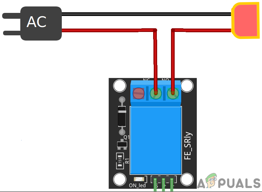
Now we will connect the relay module to the transistors. Make sure that the first transistor is connected to the pin34 of the ESP module and the second transistor is connected to the pin35 of the ESP module. We will use both the relay modules in normally open mode. Connect the gas valve and the spark plug to the output terminal of the first and second relay module respectively. Make sure that you connect the relay module ass shown in the picture below.
Step 4: Working
The heart of this project is the ESP32 that is the microcontroller board. A gas valve and a spark plug are connected to the ESP via relay modules. The gas valve is initially closed. When it is switched on from the mobile application, the gas valve is switched on. Same in the case of the spark plug. It can be switched o or off through the mobile app. This spark plug will be connected to the stove where the gas is released. This spark plug will light the fire.
Step 5: Getting Started With ESP32
If you haven’t worked on Arduino IDE before, don’t worry because a step by step to set up Arduino IDE is shown below.
- Download the latest version of Arduino IDE from Arduino.
- Connect your Arduino board to the PC and open Control Panel. Click on Hardware and Sound. Now open Devices and Printer and find the port to which your board is connected. In my case it is COM14 but it is different in different computers.

Finding Port - Click on File and then click on Preferences. Copy the following link in the Additional Board Manager’s URL. “https://dl.espressif.com/dl/package_esp32_index.json”
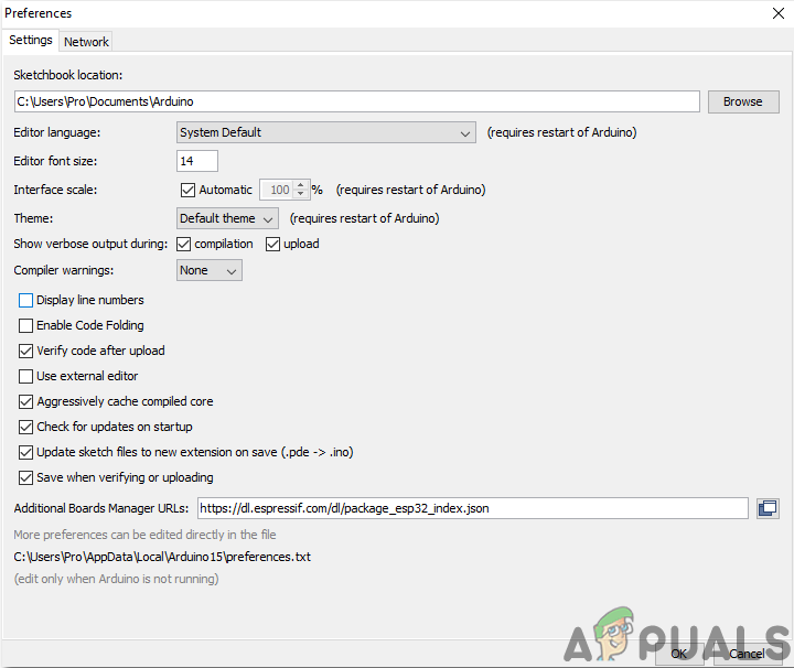
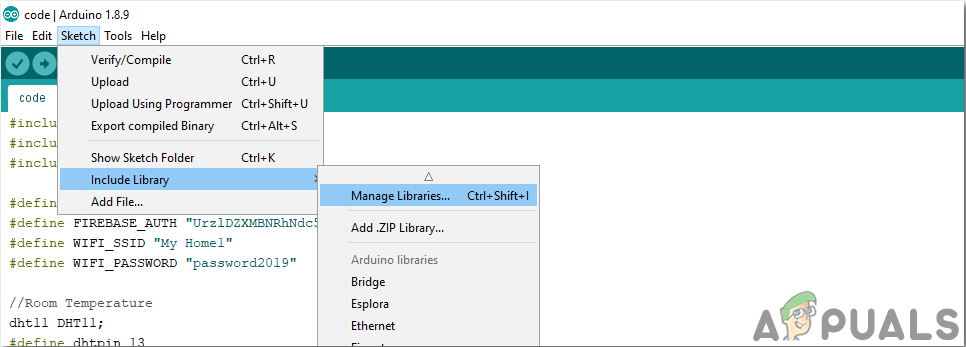
Preferences - Now, to use ESP32 with Arduino IDE, we need to import special libraries that will allow us to burn code on ESP32 and use it. these two libraries are attached in the link given below. To include the library, goto Sketch > Include Library > Add ZIP Library. A box will appear. Find the ZIP folder on your computer and click OK to include the folders.
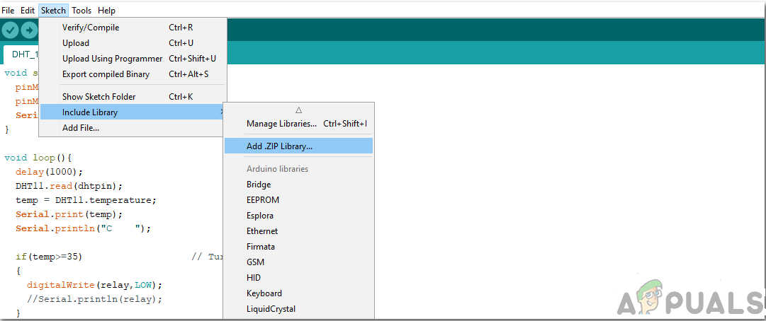
Include Library - Now goto Sketch > Include Library > Manage Libraries.
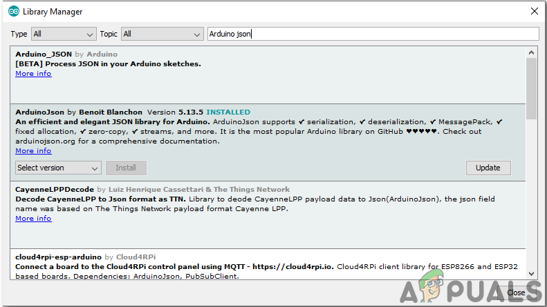
Manage Libraries - A Menu will open. In the search bar, type Arduino JSON. A list will appear. Install Arduino JSON by Benoit Blanchon.
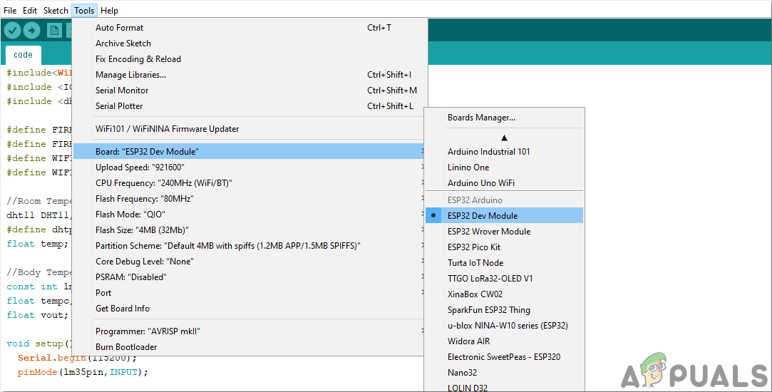
Arduino JSON - Now click on the Tools. A dropdown menu will appear. Set the board to ESP Dev Module.
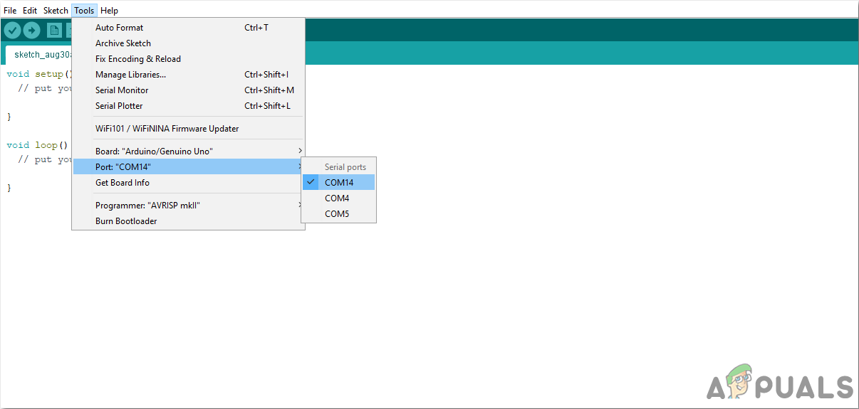
Setting Board - Click on the Tool menu again and set the port that you observed in the control panel before.
Setting Port - Now Upload the code that is attached in the link below and click on the upload button to burn the code on the ESP32 microcontroller.
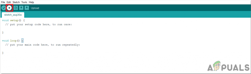
Upload
So now when you will upload the code, an error may occur. This is the most common error that may occur if you are using a new version of the Arduino IDE and the Arduino JSON.
There is nothing to worry about because we can eliminate these errors by following some simple steps. These errors are arising because the new version of Arduino JSON has another class instead of StaticJsonBuffer. This is the class of JSON 5. So we can simply eliminate this error by downgrading the version of Arduino JSON of our Arduino IDE. Simply go to Sketch > Include Library > Manage Libraries. Search for Arduino JSON by Benoit Blanchon that you have installed before. Uninstall it first and then set its version to 5.13.5. Now as we have set an old version of Arduino JSON, install it again and recompile the code. This time, your code will compile successfully.
To download the code, click here.
Step 6: Code
The code attached is pretty well commented but still, some of its parts are explained below.
1. At the start, two libraries are included so that WiFi is enabled and the ESP board can be connected to the firebase database. Then the firebase host, authentication, the name of your local wifi connection and the password of the same wifi connection is included. Also, define the pins on the ESP board that will be used to connect the external devices.
#include<WiFi.h>                   // include library to use WiFi
#include <IOXhop_FirebaseESP32.h>  // include library to connect to Firebase

#define FIREBASE_HOST "xxxxxxxxxx" // replace xxxxxxxxxx by your firebase host here
#define FIREBASE_AUTH "xxxxxxxxxx" // replace xxxxxxxxxx by your firebase authentication here
#define WIFI_SSID "xxxxxxxxxx"     // replace xxxxxxxxxx by the name of our Wifi connection
#define WIFI_PASSWORD "xxxxxxxxxx" // replace xxxxxxxxxx by your wifi password

#define valve 34                   //connect gas valve to this pin
#define spark 35                   //connect spark plug to this pin
2. void setup() is a function that runs only once when the microcontroller is powered on or the enable button is pressed. In this function, the baud rate is set, which is basically the communication speed in bits per second. After that, the ESP board is connected to the Wifi.
void setup() {
Serial.begin(115200);     // set baud rate
pinMode(valve,OUTPUT);    // set pin 34 to be used as OUTPUT
pinMode(spark,OUTPUT);    // set pin 35 to be used as OUTPUT

// connect to wifi.
WiFi.begin(WIFI_SSID, WIFI_PASSWORD);
Serial.println("connecting");
while (WiFi.status() != WL_CONNECTED) {
Serial.print(".");
delay(500);
}
Serial.println();
Serial.print("connected: ");
Serial.println(WiFi.localIP());
Firebase.begin(FIREBASE_HOST, FIREBASE_AUTH);
}
3. Void loop() is the function that runs repeatedly in a loop. In this loop, the values are being read from the firebase and are examined that if they are zero or one. If the values are one, then a HIGH signal is sent to the pin that will result in turning the relay module on. If the value is zero, a LOw signal will be sent to the pin of ESP which will result in turning the relay off.
void loop() {

// get value
temp1 = Serial.println(Firebase.getFloat("light")); // get the value for the switcching of the gas valve
temp2 = Serial.println(Firebase.getFloat("AC"));   // get the vaue for the switching of spark plug

if(temp1 == 1)
{
digitalWrite(valve,HIGH) // turn on relay one
}
else if(temp1 == 0)
{
digitalWrite(valve,LOW) // turn off relay one
}
else if(temp2 == 1)
{
digitalWrite(spark,HIGH) // turn on relay two
}
else if(temp2 == 0)
{
digitalWrite(spark,LOW) // turn off relay two
}

// handle error
if (Firebase.failed()) {
Serial.print("setting /number failed:");
Serial.println(Firebase.error());
return;
}
delay(1000);
}
That’s all for today. Now, you can make our own smart stove at home. Keep checking our site for more interesting articles like these in the future.