How To Control Your Air Conditioner With Your Smartphone Instead Of The Remote?
In the modern world, if we look around, we can see that everything that includes electronics is automated to some extent. The latest automation techniques are adopted by a few people in their homes. In this modern era, people should opt for the latest automation techniques to make their life easier. Normally in our homes, we turn ON, OFF and set the temperature manually in our air conditioners. Nowadays, a single component like a relay module can be used to control various electronic parameters of a house, for example, switching of home appliances, monitoring of security alarms, garage door automation, etc. In this article, we are going to develop a system that will allow you to control your air conditioner by using a mobile application instead of its remote. As an android mobile is the most common among the people, so an android application is the best option to control our air conditioner.
How To Setup All The Necessary Peripherals With ESP32?
To make any project, one must know what the basic components that one is going to need to complete it are. So an excellent approach before starting the work is to make a complete list of all the components to save time and to avoid the chance of getting stuck in the middle of the project. A complete list of all the components that are easily available in the market is given below. After arranging the hardware components we will design our own android application for controlling our air conditioner :
Step 1: Components Used (Hardware)
- ESP32
- MakerFocus I2C OLED Display Module
- No products found.
- Push Button Switch
- IR Receiver
- No products found.
- No products found.
- Jumper Cables
- TSOP Receiver
- Breadboard
- Android Charger
Step 2: Components Used (Software)
As we are going to make a wireless switch, we will need a button to turn it on and off. We want to use a mobile phone to operate this button so we will need to develop an application for that. The most convenient application is an android application and we need to install these two software to connect to that application. Both of them are listed below:
Step 3: Installing Android Studio
Before installing Android Studio, we will install JAVA JDK first. To install this, click on the exe file that you downloaded from the above link, and click next until it is successfully installed. Now Go through the following steps so that your command prompt recognizes java as an external or internal command.
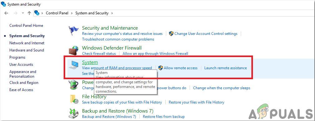
- Open Control Panel and click on System and Security.
- Click on System.
System - Click on Advanced System Setting and then click on Environmental Variables.
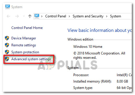
Advanced System settings - In the System Variable section, click on the path and then click on edit. A new Edit Environmental Variable box will appear.
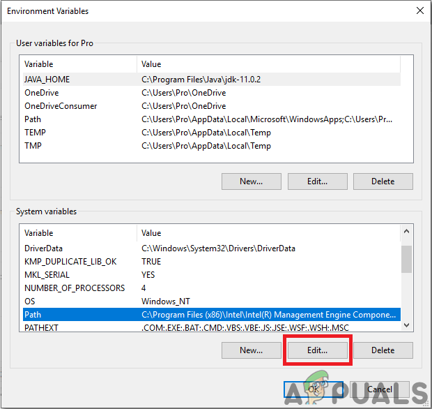
Edit Path - Now go to C:\Program Files\Java in your PC. Open the JDK folder, click on the bin folder and then copy the path of that folder.
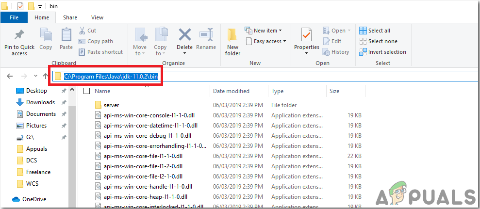
Path Of Bin Folder - Now go to the Edit Environmental Variable box and click on new to make a new variable. Paste the path that you copied in the above step in the new variable and save it.
- Now to confirm, if it is completely installed, open command prompt and type java –version.
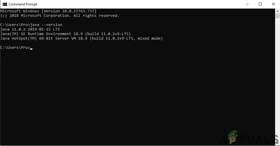
JAVA version
Now as you have successfully installed Java JDK on your computer. Let us now install Android Studio on your computer. Installing this software is very easy. You need to open the downloaded file and click next until your software is fully installed.
Step 4: Connection To Firebase
Now as we have installed Android Studio, let us launch it and make a new project to connect it to the firebase. To do this, follow the following steps.
- Launch Android Studio and make a new project by clicking on the Empty Activity.
- Now name your project as computerSwitc, select Kotlin as language, and select the minimum API level according to your mobile phone.
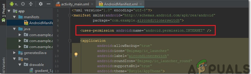
- Since we are going to use the internet to control the pins of the raspberry pi. We will set permission in our app to access local wifi. To do this, go to app > manifests > AndroidManifest.xml and add the following command.<uses-permission android:name=”android.permission.INTERNET” />
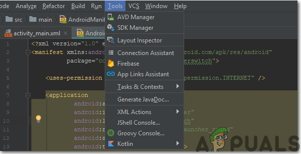
Internet Permission - Now, click n Tools. A drop-down menu will appear from which, select Firebase.
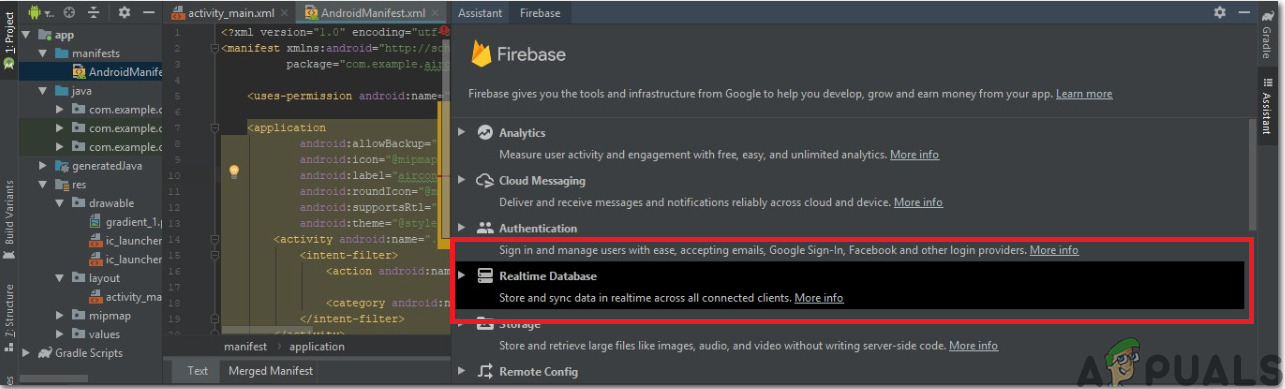
Firebase Connection - A big menu will appear on the right side of the screen that will be providing the menu of almost every service that firebase is providing. But right now our main focus is on Real-Time Database. So click on Real-Time Database. A link to “Save and Retrieve Data” will appear. Click that link.
Firebase Assistant - Connect on Connect To Firebase button. It will take you to the default web browser. First, it will ask you to log-in to your Gmail account. Then click on Add the Realtime Database to your app and accept the changes.
- Now go to Firebase Console. There you will see a project already made. The android logo on that projet’s icon means that it already belongs to an android application.
- From the Develop menu that appears on the left side of the screen, select Database. A button of Create Database will appear on the right. Click on that button.
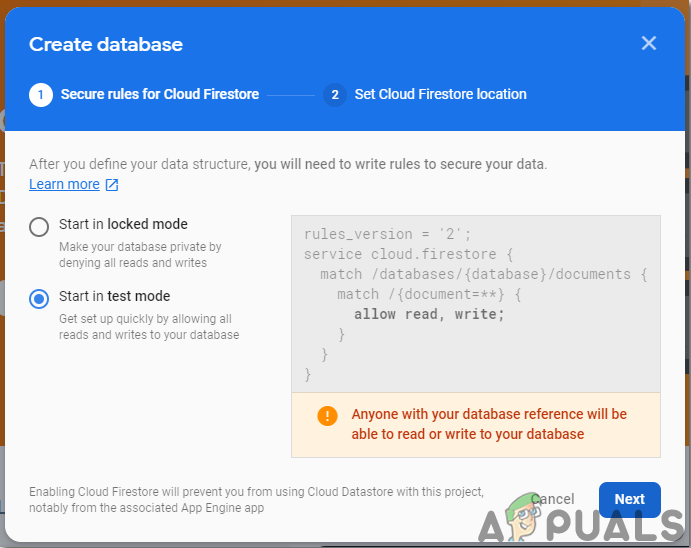
- A menu will appear asking to set the mode of your database. Click on test mode and then click Enable.
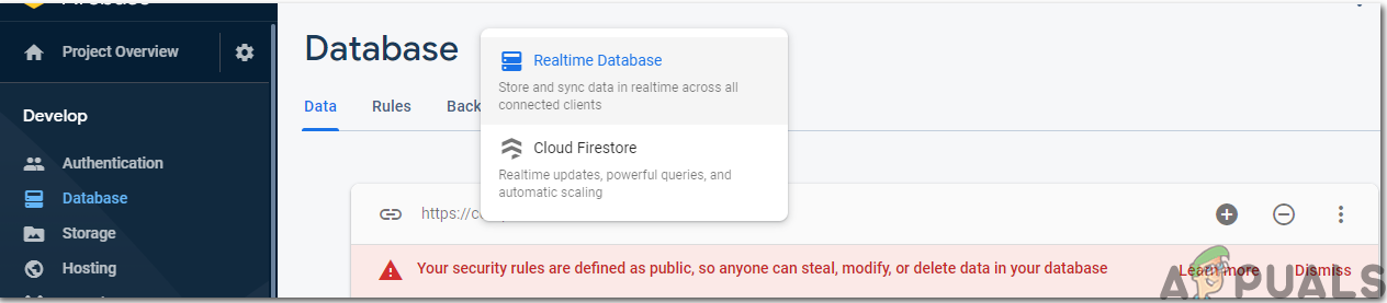
Test Mode - Now a really important step to remember is to change the Cloud Firestore to Real-Time Database. To do so click on the button shown in the below image and change the desired option.
Realtime Firebase - Now click on the Rules tab and change the configurations to True. Once everything is done, click Publish.
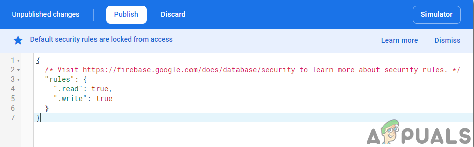
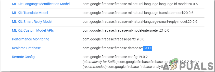
Changing Configurations - One thing that you need to do other than connecting the firebase, is to update the database version. For that, click on go to docs. Now click on guides and select Android Guides from the list that appears on the screen. Scroll down until a table appears. Look for Real-Time Database in that table and find its version. in my case, it is 19.1.0.
Version - . Click on Gradle Scripts, a menu on the left side of the screen. Then select built. gradle (Module: app). Now in the code, search for the version of the Real-Time database and replace it by the new one.
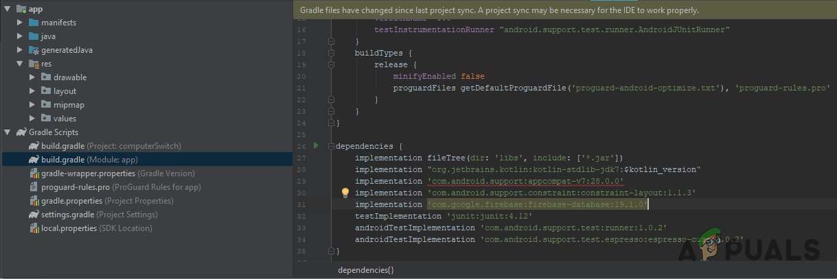
Firebase Version - Now sync the project by clicking on the sync button appearing on the top of the screen.
Step 5: Making Layout
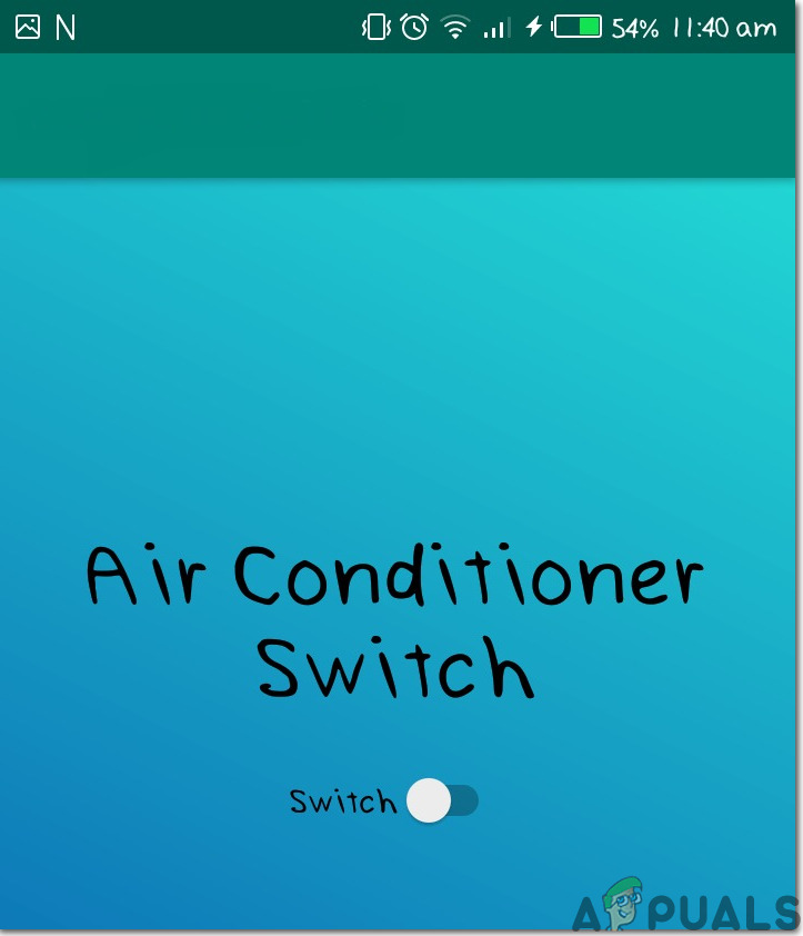
Now, as our android application is connected to the firebase, let us make a layout of our app that will be used by the user to switch the computer on or off. To make a layout, go to app > res > layout > activity_main.xml. where we will design a layout. Copy the code given here to make a text view.
The layout of our app will look like this:
Step 6: Getting Started With ESP32
If you haven’t worked on Arduino IDE before, don’t worry because a step by step to set up Arduino IDE is shown below.
- Download the latest version of Arduino IDE from Arduino.
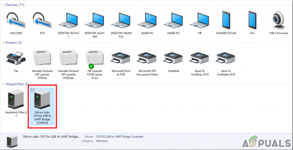
- Connect your Arduino board to the PC and open Control Panel. Click on Hardware and Sound. Now open Devices and Printer and find the port to which your board is connected. In my case it is COM14 but it is different in different computers.
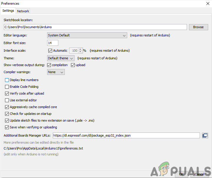
Finding Port - Click on File and then click on Preferences. Copy the following link in the Additional Board Manager’s URL. “https://dl.espressif.com/dl/package_esp32_index.json”
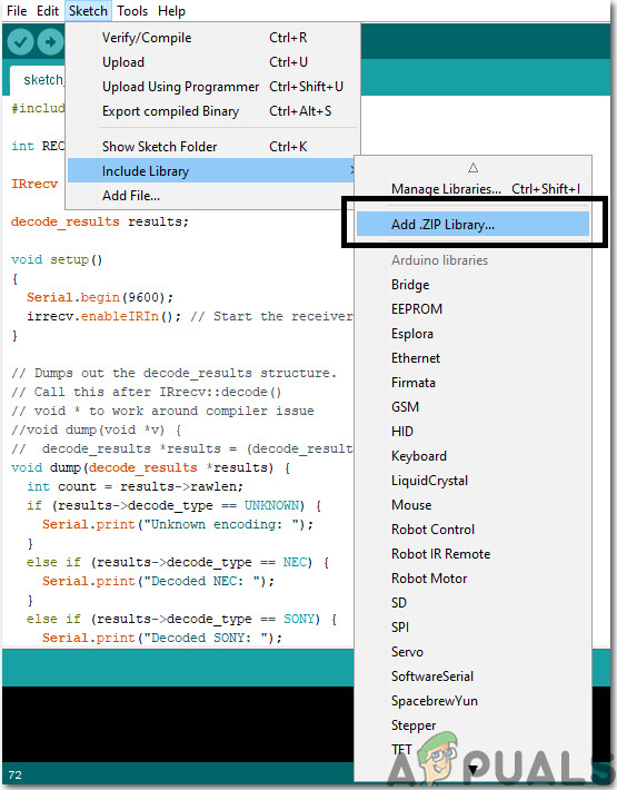
Preferences - Now, to use ESP32 with Arduino IDE, we need to import special libraries that will allow us to burn code on ESP32 and use it. these two libraries are attached in the link given below. To include the library, goto Sketch > Include Library > Add ZIP Library. A box will appear. Find the ZIP folder on your computer and click OK to include the folders.
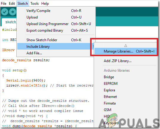
Including Library - Now go to Sketch > Include Library > Manage Libraries.
Manage The Libraries - A Menu will open. In the search bar, type Arduino JSON. A list will appear. Install Arduino JSON by Benoit Blanchon.
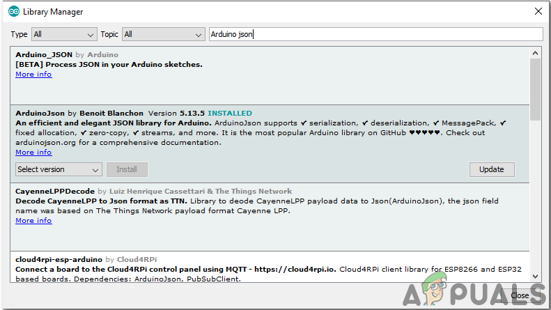
Arduino JSON - Now click on the Tools. A dropdown menu will appear. Set the board to ESP Dev Module.
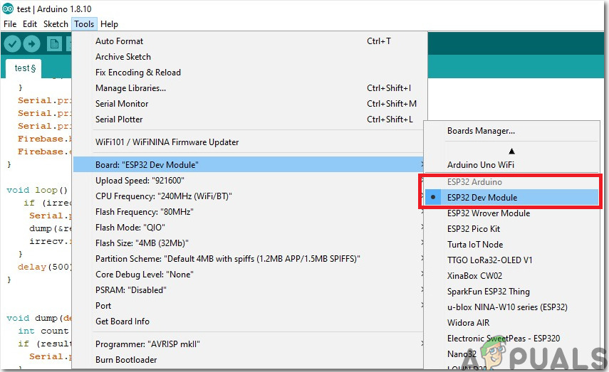
Setting The Board - Click on the Tool menu again and set the port that you observed in the control panel before.
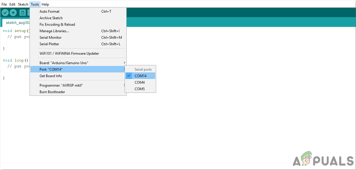
Setting Port - Now Upload the code that is attached in the link below and click on the upload button to burn the code on the ESP32 microcontroller.
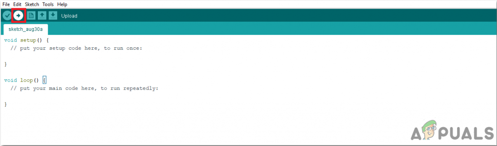
Upload
So now when you will upload the code, an error may occur. This is the most common error that may occur if you are using a new version of the Arduino IDE and the Arduino JSON. The following are the errors that you may see on the screen.
In file included from C:\Users\Pro\Documents\Arduino\libraries\IOXhop_FirebaseESP32-master/IOXhop_FirebaseESP32.h:8:0,

from C:\Users\Pro\Desktop\airconditioner\code\code.ino:2:

C:\Users\Pro\Documents\Arduino\libraries\IOXhop_FirebaseESP32-master/IOXhop_FirebaseStream.h:14:11: error: StaticJsonBuffer is a class from ArduinoJson 5. Please see arduinojson.org/upgrade to learn how to upgrade your program to ArduinoJson version 6

StaticJsonBuffer<STREAM_JSON_BUFFER_SIZE> jsonBuffer;
^
In file included from C:\Users\Pro\Documents\Arduino\libraries\IOXhop_FirebaseESP32-master/IOXhop_FirebaseESP32.h:8:0,

from C:\Users\Pro\Desktop\airconditioner\code\code.ino:2:

C:\Users\Pro\Documents\Arduino\libraries\IOXhop_FirebaseESP32-master/IOXhop_FirebaseStream.h:65:11: error: StaticJsonBuffer is a class from ArduinoJson 5. Please see arduinojson.org/upgrade to learn how to upgrade your program to ArduinoJson version 6

return StaticJsonBuffer<STREAM_JSON_DATA_BUFFER_SIZE>().parseObject(_data);

^
Multiple libraries were found for "WiFi.h"

Used: C:\Users\Pro\AppData\Local\Arduino15\packages\esp32\hardware\esp32\1.0.2\libraries\WiFi

Not used: C:\Program Files (x86)\Arduino\libraries\WiFi

Using library WiFi at version 1.0 in folder: C:\Users\Pro\AppData\Local\Arduino15\packages\esp32\hardware\esp32\1.0.2\libraries\WiFi

Using library IOXhop_FirebaseESP32-master in folder: C:\Users\Pro\Documents\Arduino\libraries\IOXhop_FirebaseESP32-master (legacy)

Using library HTTPClient at version 1.2 in folder: C:\Users\Pro\AppData\Local\Arduino15\packages\esp32\hardware\esp32\1.0.2\libraries\HTTPClient

Using library WiFiClientSecure at version 1.0 in folder: C:\Users\Pro\AppData\Local\Arduino15\packages\esp32\hardware\esp32\1.0.2\libraries\WiFiClientSecure

Using library ArduinoJson at version 6.12.0 in folder: C:\Users\Pro\Documents\Arduino\libraries\ArduinoJson

exit status 1

Error compiling for board ESP32 Dev Module.
There is nothing to worry about because we can eliminate these errors by following some simple steps. These errors are arising because the new version of Arduino JSON has another class instead of StaticJsonBuffer. This is the class of JSON 5 actually. So we can simply eliminate this error by downgrading the version of Arduino JSON of our Arduino IDE. Simply go to Sketch > Include Library > Manage Libraries. Search for Arduino JSON by Benoit Blanchon that you have installed before. Uninstall it first and then set its version to 5.13.5. Now as we have set an old version of Arduino JSON, install it again and recompile the code. This time, your code will compile successfully.
Step 7: Understanding The Code
The code of this project is very simple and it is briefly explained below. Furthermore, the code with the necessary libraries can also be downloaded from Here.
1. At the start, we need to include two libraries that will be used to connect our code to the Firebase database and the second one to use the IR sensor with our microcontroller. Then we will add the host and authentication of our firebase because after that our ESP32 would be able to find our database. Then we will provide the SSID and the password of our local internet connection. Then, we have to make an object so that we could push and pop data from our cloud. Then we will define the pin to which our sensor will be connected and we will also make an object to handle data coming from the IR sensor.
#include<WiFi.h>
#include <FirebaseESP32.h>
#include <IRremote.h>

#define FIREBASE_HOST "coma-patient.firebaseio.com"
#define FIREBASE_AUTH "UrzlDZXMBNRhNdc5i73DRW10KFEuw8ZPEAN9lmdf"
#define WIFI_SSID "PRO"
#define WIFI_PASSWORD "abcdefgh"

FirebaseData firebaseData;
int RECV_PIN = 19;
IRrecv irrecv(RECV_PIN);
decode_results results;
2. void setup(), is the loop that runs when the enable button is pressed or when the microcontroller is powered on. Here we will start the receiver of our IR sensor and write the code to start connecting our microcontroller to the local internet connection.
void setup() {
Serial.begin(115200);
pinMode(RECV_PIN,INPUT);
irrecv.enableIRIn(); // Start the receiver

// connect to wifi.
WiFi.begin(WIFI_SSID, WIFI_PASSWORD);
Serial.println("connecting");
while (WiFi.status() != WL_CONNECTED) {
Serial.print(".");
delay(500);
}
Serial.println();
Serial.print("connected: ");
Serial.println(WiFi.localIP());
Firebase.begin(FIREBASE_HOST, FIREBASE_AUTH);
Firebase.enableClassicRequest(firebaseData, true);
}
3. void loop() is a function that runs repeatedly in a loop. Here this code is checking if the values are coming from the sensor.
void loop() {
if (irrecv.decode(&results)) {
Serial.println(results.value, HEX);
dump(&results);
irrecv.resume(); // Receive the next value
}
delay(500);
}
4. void dump() is a function that is used to first identify the model of the remote that is sending the signal to the sensor. it also dumps out the decode_results structure.
void dump(decode_results *results) {
int count = results->rawlen;
if (results->decode_type == UNKNOWN) {
Serial.print("Unknown encoding: ");
}
else if (results->decode_type == NEC) {
Serial.print("Decoded NEC: ");
}
else if (results->decode_type == SONY) {
Serial.print("Decoded SONY: ");
}
else if (results->decode_type == RC5) {
Serial.print("Decoded RC5: ");
}
else if (results->decode_type == RC6) {
Serial.print("Decoded RC6: ");
}to
else if (results->decode_type == PANASONIC) {
Serial.print("Decoded PANASONIC - Address: ");
Serial.print(results->panasonicAddress,HEX);
Serial.print(" Value: ");
}
else if (results->decode_type == JVC) {
Serial.print("Decoded JVC: ");
}
Serial.print(results->value, HEX);
Serial.print(" (");
Serial.print(results->bits, DEC);
Serial.println(" bits)");
Serial.print("Raw (");
Serial.print(count, DEC);
Serial.print("): ");

for (int i = 0; i < count; i++) {
if ((i % 2) == 1) {
Serial.print(results->rawbuf[i]*USECPERTICK, DEC);
}
else {
Serial.print(-(int)results->rawbuf[i]*USECPERTICK, DEC);
}
Serial.print(" ");
}
Serial.println("");
}
Step 8: Preparing The Hardware
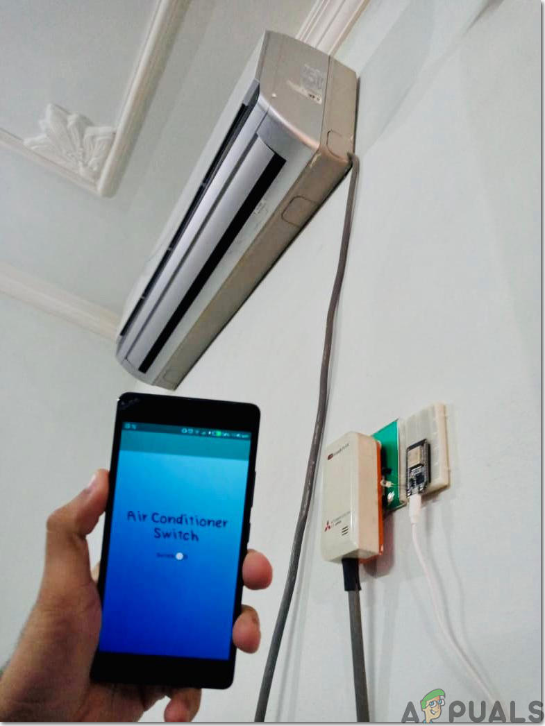
After burning the code into the ESP32, we need to prepare the hardware and attach it to the wall or any other suitable place near the air conditioner. Attach the components onto the breadboard by following the diagram presented at the top. After assembling the circuit power up the ESP module using the Android Charger. It is better to design the casing of the hardware at home or simply put the hardware inside the Raspberry Pi case.
Step 9: Giving Final Touches
After assembling the hardware we will test it. Connect the android charger to the ESP32 and power it on and make sure your phone has good strength of signals of your local internet connection. Open your application and press the button, you will see that you can now control your AC with your mobile application.
That was all for today, I hope you would have enjoyed reading this article and after making your own prototype for controlling your air conditioner at home don’t forget to share your experience!